- Joined
- Feb 13, 2016
- Messages
- 96
- Reaction score
- 29
- Age
- 66
Joe,
As result of your investigation and summation as presented on this prop balancer, I was curious if you had presented your findings to the seller, and if there was any response offered by EJH in that regard.
I have order this balancer for its ease of use over the laser pointer method, but now from what you've mentioned I may need to return the balancer if it doesn't work as advertised, or I too find that further disassembly of the motor hub assembly is required to perform a proper prop balancing.
Btw, wouldn't it be in your best interest to simply return the balancer under the Amazon satisfaction policy rather than selling to another for less than half the cost you had paid for balancer & shipping costs. : )
Hi Skynet,
Yeah, I contacted EJH but haven't heard anything back yet. I have a feeling they will continue selling those balancing adapters for those who don't care if everything is really balanced right or not.
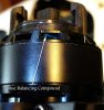
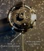
I removed the hubs from the motors (one for each direction, so you have to remove two hubs) but when I spooled the motors up without the hubs on they were definitely out of balance, that's how I found out for sure the locking tabs on those hubs are part of the balance of the motors too. I suspected that would be the case at first glance, then confirmed it by testing it out while using an official machine shop vibration meter (not the app), the meter showed a lot of X, Y axis movement (sideways vibrations) but hardly any Z axis movement (Vertical).
A small part of those locking tabs add weight to the center part of the prop, so, IMHO, there's just no way to truly balance them without using the laser method.
As mentioned before, the motors, hubs and props all work together as one system.
I really wish I had been able to balance them without using the laser method cause it does take time and patience but it just doesn't work that great using traditional balancing methods.
If the locking tabs would lock-in at a 90° angle to the longitudinal (length of the chord) axis of the prop, you could probably just balance it to the point where it rests perfectly horizontal when but the locking tabs lock-in at about a 45° angle. I thought about not locking them in all the way but that throws it off from where they set when in use on the motors.
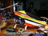
The main reason I started using the laser method with my S800 and S1000 is to use the prop to perfectly balance the motors at the same time. I've found that the motors aren't balanced exactly true either. The motors not being as balanced as possible cause premature bearing wear as well so it just made better sense to balance everything by laser.
If the motors weren't perfectly balanced, you could use any prop on any motor (not considering the counter rotation thing) but since they aren't, I mark the props so they go back on the motor it was balanced on.
Another issue for me, is the vibrations imposed on the electronics and other parts of the Inspire (and others). I've found that the IMU and other sensors work better, longer and are more reliable if they aren't subjected to those vibrations from the props "and" motors. Remember, the only part really dampened from vibrations is the gimbal, everything else feels that vibration!
A short story about my S800 when I first got it:
I couldn't get the thing to sit still in a stable hover even though it was locked onto 12 or so satellites and the GPS receiver was offset for magnetic north in our area (it didn't have the toilet bowl effect thing going on), it just wouldn't stay put even in calm wind. It wouldn't drift off far but it was trying to hit that GPS positioning wall with the gain set in the medium range. It was trying to drift to the left and the IMU was definitely level and held firmly in place by a strap and a thin piece of foam tape as prescribed. I tested the outputs of the IMU and ESCs with my Oscilloscope and found it to be operating normal in all axis. I kept calling DJI and asking around until I finally decided to check for vibrations. Alas, that was the culprit. I laser balanced every prop and motor and it immediately flew the way it was supposed to. The gimbal even behaved much better (I kept having to try different durometer values on the damper balls). After the balance was completed, I was able to go back to the original damper balls for the gimbal.
I performed a rather risky test one day after the balancing part was finished. I strapped the whole MR to the workbench and set the legs on a piece of high density foam rubber, then I spooled all of the motors up at once. After putting on a face shield and protective welding leather, I reached down from under table level to put my hands on the arms near the center hub just to see if it felt smooth and I couldn't feel any vibrations whatsoever. ;-) I DO NOT recommend that anyone try that, looking back on it, I shouldn't have done it either. I should have used a long, thin fiberglass rod to test for vibrations.
As mentioned earlier, I know this is a lot of trouble but in reality, once you've set everything up, it only takes about an hour to an hour and a half to balance all 8 props (including the 4 spare props).
Then, when the props wear down and get too sloppy and need to be replaced, it's not that bad to do again since the initial setup has already been done.
Only speaking for myself here, I tested the vibrations on the Inspire frame before the laser balance thing, then tested it afterwards (with my machine shop vibration meter) and there was a major reduction in vibration to the frame and all of the electronics.
I can't help but believe (after all of my tests and seeing the results) that minimizing the vibrations at the frame level wouldn't make the on-board sensors such as the IMU and other sensors much more reliable in-flight.
I had a few highly erratic readings on the IMU sensors with the Inspire in a stable hover in perfectly calm wind before the balance job. Now they are all very stable a hover and in-flight. I only flew it a couple of times before balancing the props and motors.
They claim the motors are perfectly balanced and some or most may very well be but mine were not.
Maybe I'm being too picky but I feel that if it's as in-tune as possible, it has to be more reliable and last longer.
That's the way I am with my machine tools in my shop (always have been), some of them are nearly 30 years old now and are still working almost as good as new!!
") To me, it does really pay off in the long run!!
To me, it does really pay off in the long run!! Sorry, I got a little carried away here, I don't usually do that.
Yes, I could return that balancer to Amazon but it hadn't crossed my mind. You're right, I should return it and I will, so, thank you for mentioning that!!!
Keep me posted and if there's anyway I can help, please let me know.
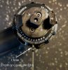
PS, I balanced a friend's Inspire yesterday and I decided to make a CD mirror with slots on the top and bottom so I could feed velcro through the slots and just strap it onto the motor/ESC housings. It's much easier to do that part now. My local hobby shop sends people to me for repairs and to have special project parts made (like for camera mounts or replacement parts that are hard to find on old or homebuilt planes, helis and MRs). I have a CAD program with a CNC milling machine and they like to have carbon fiber parts made for them sometimes. They just bring me the measurements with a rough drawing, then I make a 3D model in the software, then send it to the milling machine to be milled out. I don't charge much of anything but I really enjoy helping them out from time to time. They are a great bunch of people!!
I have a feeling you all are a great bunch of people as well!! I hope all of this has helped!!
Joe
")


 I'm really disappointed with this new finding. I didn't look there before because every outrunner I've ever seen was balanced on the inside.
  )
)