IMG_2077
Use 6s batteries, (not 3s) on each leg and put 1 splice into each side
")
6s 1800 on each leg for a total of 3600 mAh should give you 30 minutes still landing at 25%


Use 6s batteries, (not 3s) on each leg and put 1 splice into each side
6s 1800 on each leg for a total of 3600 mAh should give you 30 minutes still landing at 25%
6S batteries would be my preference, but unfortunately there aren't a ton of options for LiHV batteries.
Still, the main problem here is that I don't know where to splice in on the Inspire 2.
I told you, use 6s packs and splice into each side.
From RC Groups
RC Groups - View Single Post - DJI Power Supply & Power Supply Talk
I can't open your attachment from dropbox until I get home, but it appears you are talking about the Inspire 1
")
cool man, much appreciated.It is not my dropbox, it is a link on RCGroups.
I will download the pic YOU posted and show u where to solder, then re upload it
cool man, much appreciated.
i am curious. was under if not the first to mod the bird side  - good old times lol...
 Fredz, so you think it makes sense to splice into the motor wires with an auxiliary battery?I though it to be enough just to remove some plastic from the wires and solder to every wire...
But not sure of course. Clearly says + and - on the wires.

Sorry, been busy.
Here's what I know.
Connect jumper leads at the point the batt packs come in, (or before any circuit boards)
Do not supply current down stream of any circuit board, always upstream, before the boards.
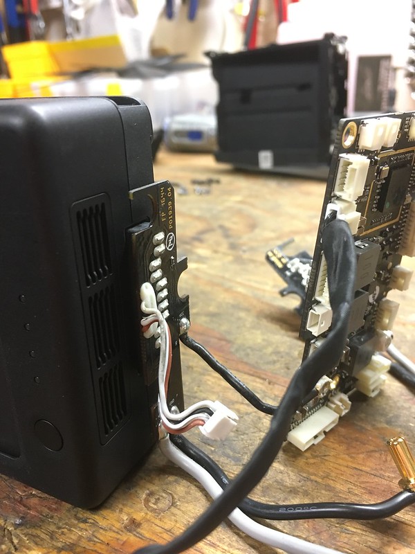
Can you post a pic of what the battery leads are actually touching when mounted on the I2?
One way I know I can solve this is what will be in the mail tomorrow. I purchased the remote controller charger cable that connects the battery to the remote control. I'll be able to disassemble that to trace back to the contacts that are actually supplying the power.
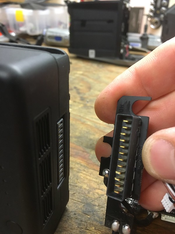
I would agree, hence the reason I don't care for the new battery design. It was much easier on the I1 when the two power contacts on the I1 battery are obvious. This is looking less and less likely without drilling into the casing around these circuit boards (something I was hoping to avoid). I also need to figure out the pin out of these batteries. I don't know which of the 12 contacts is the positive and negative terminals that supply the large current for the motors.
I need to look at the dropbox thing again. It was only a picture of the the I1 when I opened it up last night. If it is more than that, then I wasn't looking hard enough. I saw that picture and didn't scroll down since I thought it would something on the I1.Might have to just mod the batteries, but i'm sure the board can be jumped.
Did you at least watch that dropbox vid, to learn whats going on with current batteries?
the positive and negative are most likely to be on the sides (in general as far as i can tell)
nevertheless the description is or should be always on the pcb for assy (assembly).
so if you take the things apart and take a closer look on the back or front you should have marks to see what is what and who is with who...
i unfortunatley do not have an I2 yet but really plan to get one in very very near future.
We use essential cookies to make this site work, and optional cookies to enhance your experience.