Hi all,
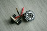
I'm seeking help with identifying exactly what the pins are for the Inspire V1 ESC (the 5-pin and the 3-pin JST GH connectors, picture attached). I've seen a similar thread for V2 (Help me figure out the pinout for the ESC signal connector) but it's for a slightly different product and I need more detailed info on the data links as I was not able to make the motors turn on my test bench just by supplying appropriate PWM signal to either of the two PWM pins and ground (successful method for other DJI ESCs).
I'm assuming that the two PWMs are for receiving data with one of the PWMs for the motor, the other for the attached LED? Do I need to send a special byte sequence over the serial link to activate/sustain/control the motor?
Detailed information on the RS485 link would be great, if it's relevant here.
Thanks a bunch!